Table of Contents
How to Use PIC10F322 for Basic Monostable Circuits: A 555 Timer Alternative
Using a PIC10F322 microcontroller as a replacement for a 555 timer in basic monostable circuits can simplify your design process and reduce the need for multiple discrete components like resistors and capacitors. This guide will show you how to achieve this with clear instructions and sample code.
Why Use PIC10F322 Instead of a 555 Timer?
Working with 555 timer circuits often involves calculating and sourcing specific resistor and capacitor values, which can be time-consuming and frustrating. By programming a PIC10F322 microcontroller, you can achieve the same functionality with greater flexibility and precision.
The Monostable Circuit
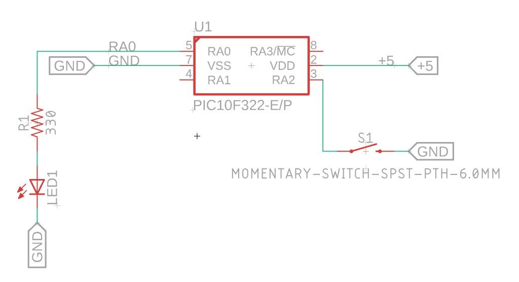
This monostable circuit will turn an output (PORTA0) high for a predetermined amount of time when a low pulse is detected on an input (PORTA2). You can easily adjust the duration that PORTA0 stays high by changing the value of PulseOut_Time in milliseconds.
About The Circuit
For the demo circuit we are using a switch on A2 – and a LED connected to A0.

XC8 Code for the Monostable Circuit
Here’s the complete XC8 code for creating a monostable circuit using the PIC10F322 microcontroller:
/*
 * File:  555_monostable.c
 * Author: Jamie Starling - jamiestarling.com
 *
 * Created on:  September 7, 2021, 7:45 PM
 *
 * Code/Circuit provided as-is.
 */


#include <xc.h>
#include <stdint.h>

//Device Configuration
#pragma config FOSC = INTOSC  // Oscillator Selection
#pragma config BOREN = ON    // Brown-out Reset
#pragma config WDTE = OFF    // Watchdog Timer
#pragma config PWRTE = ON    // Power-up Timer
#pragma config MCLRE = OFF   // MCLR Pin Function Select bit->MCLR pin function is digital input, MCLR internally tied to VDD
#pragma config CP = OFF      // Code Protection
#pragma config LVP = OFF     // Low-Voltage Programming
#pragma config LPBOR = ON    // Brown-out Reset Selection bits
#pragma config BORV = LO    // Brown-out Reset Voltage Selection
#pragma config WRT = OFF    // Flash Memory Self-Write Protection

//Used to calculate the delay time - Change depending on processor Speed
#define _XTAL_FREQ 8000000  //8Mhz

#define PulseOut_Time 1000

//Prototypes
void setup(void);


void main(void)
{
    setup();

    while(1)
    {
        if (PORTAbits.RA2 == 0)
        {
            LATAbits.LATA0 = 1;
            __delay_ms(PulseOut_Time);
            LATAbits.LATA0 = 0;
        }
    }
}

void setup(void)
{

    //Disable analog for A0, set as Output, Set to Low
    ANSELAbits.ANSA0 = 0;
    TRISAbits.TRISA0 = 0; //A0 Output
    LATAbits.LATA0 = 0;  //Put A0 low

      //Setup A2 as input with WPU
    ANSELAbits.ANSA2 = 0;
    TRISAbits.TRISA2 = 1;
    WPUAbits.WPUA2 = 1; //Enable Weakpull up on A2
    OPTION_REGbits.nWPUEN = 0; //Requires being enabled in option reg as well

}
Adjusting the Pulse Duration
To change the duration that PORTA0 remains high, modify the PulseOut_Time value in milliseconds. For example, setting it to 2000 will keep PORTA0 high for 2 seconds.
Summary
Using a PIC10F322 as a replacement for a 555 timer in a basic monostable circuit provides a flexible and programmable solution. This guide walks you through the setup and code needed to create a monostable circuit with a trigger input and adjustable pulse duration. By leveraging the capabilities of the PIC10F322, you can simplify your circuit design and avoid the hassle of calculating and sourcing specific resistor and capacitor values.
Need a Creator Alchemist on Your Project?
I’m available for hire—consulting, systems design, embedded tech, creative problem-solving, or anything in between.
If you’ve got a project that needs someone who can think it through and build it out, I’m interested.
👉 Let’s Talk
jamie@jamiestarling.com
