Table of Contents
Introduction to Timer0 on PIC10F322
The PIC10F322 microcontroller includes two Timer modules: Timer0 (TMR0) and Timer2. This guide focuses on Timer0, an 8-bit timer/counter that can be incremented by either an external signal or the internal instruction clock (FOSC/4). When the timer overflows (reaches 0xFF and rolls over to 0x00), it sets an interrupt flag that can trigger an interrupt if configured.
Timer0 Modes
Counter Mode:
- In this mode, Timer0 increments on every rising or falling edge of the T0CKI pin.
- To select 8-bit Counter mode using the T0CKI pin, set the T0CS bit in the OPTION_REG register to ‘1’.
Timer Mode:
- In Timer mode, Timer0 increments every instruction cycle if used without a prescaler.
- To select 8-bit Timer mode, clear the T0CS bit of the OPTION_REG register.
Timer0 Prescaler
A programmable prescaler can be used with Timer0. The prescaler assignment is controlled by the PSA bit of the OPTION_REG register. To assign the prescaler to Timer0, clear the PSA bit to ‘0’. The prescaler options range from 1:2 to 1:256, selectable via the PS<2:0> bits of the OPTION_REG register.
Understanding the Prescaler:
- Without a prescaler, Timer0 increments by 1 for every pulse.
- With a 1:4 prescaler, Timer0 increments by 1 for every 4 pulses, effectively dividing the input frequency by 4.
Practical Example: LED Blinker Using Timer0
In this example, we will replace the LED blinker code that uses the __delay_ms macro with Timer0. This approach saves program memory space and allows the CPU to perform other tasks.
Code Overview
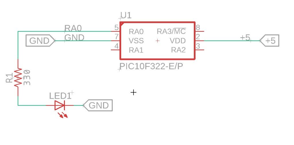
The code sets the PIC10F322 to run at 31kHz, configures Timer0 to use a prescaler of 16, and toggles an LED connected to PORTA.0 based on Timer0 overflow events.
Logic Scope View

Circuit

The Code
/*
 * File:  timer0_example.c
 * Author: Jamie Starling - GizoFoundry.com
 *
 * Created on:  September 7, 2021, 7:45 PM
 *
 * Code/Circuit provided as-is.
 */


#include <xc.h>
#include <stdint.h>

//Device Configuration
#pragma config FOSC = INTOSC  // Oscillator Selection
#pragma config BOREN = ON    // Brown-out Reset
#pragma config WDTE = OFF    // Watchdog Timer
#pragma config PWRTE = ON    // Power-up Timer
#pragma config MCLRE = OFF   // MCLR Pin Function Select bit->MCLR pin function is digital input, MCLR internally tied to VDD
#pragma config CP = OFF      // Code Protection
#pragma config LVP = OFF     // Low-Voltage Programming
#pragma config LPBOR = ON    // Brown-out Reset Selection bits
#pragma config BORV = LO    // Brown-out Reset Voltage Selection
#pragma config WRT = OFF    // Flash Memory Self-Write Protection

//Used to calculate the delay time - Change depending on processor Speed
#define _XTAL_FREQ 31000  //31Khz


//Prototypes
void setup(void);


void main(void)
{
    setup();

    while(1)
    {
          if (INTCONbits.TMR0IF == 1)  //Check to see if the overflow TMR0 flag is set
          {
              INTCONbits.TMR0IF = 0; //Clear the TMR0 interrupt flag

              LATA ^= 0b00000001;  //Use XOR and mask to flip the bits what is on becomes off.
          }
    }
}

void setup(void)
{
    //Set the System Clock - You can change this to match the setting you are looking for
    OSCCONbits.IRCF = 0b000;  //Set System Clock to 31Khz

    TMR0 = 0;  //Set TMR0 to 0
    INTCONbits.TMR0IF = 0; //Clear the TMR0 interrupt flag

    OPTION_REGbits.PS = 0b011;  //Set TMR0 Prescale to 16
    OPTION_REGbits.PSA = 0; //Assign Prescaler to TMR0
    OPTION_REGbits.T0CS = 0; //Set TMR0 Clock source to FOSC

    /*With a 31Khz clock we get.. OSC/4 7.75Khz instruction clock.
    * TMR0 increments every 129us. Without a prescaler 1/7750
     * Adding in a prescaler of 16.
     * TMR0 increments every 2ms  129 x 16
     * TMR0 overflows every 255 cycles, we get 510ms per overflow.
     */

    ANSELAbits.ANSA0 = 0;
    TRISAbits.TRISA0 = 0;
    LATAbits.LATA0 = 0;

}
Explanation of the Code
- Configuration Bits:
- The configuration bits set various hardware options like the oscillator selection and watchdog timer.
- Setup Function:
- Disables the analog functions on PORTA.
- Sets PORTA.0 as an output.
- Configures Timer0 with an internal clock source, assigns the prescaler, and sets the prescaler value.
- Main Function:
- Continuously checks for Timer0 overflow events.
- Toggles the LED on PORTA.0 when an overflow occurs and clears the overflow flag.
Timer0 Calculation Example
With a 31kHz clock:
- FOSC/4 gives a 7.75kHz instruction clock.
- Timer0 increments every 129μs (1/7750) without a prescaler.
- With a prescaler of 16, Timer0 increments every 2ms (129μs x 16).
- Timer0 overflows every 255 increments, resulting in a total overflow period of approximately 510ms.
Summary
Using Timer0 on the PIC10F322 provides a flexible and efficient way to handle timing tasks without relying on software delays. By understanding and configuring the Timer0 module, you can create precise timing functions for various applications. This guide walks you through the setup and usage of Timer0, offering a practical example to get you started.
Need a Creator Alchemist on Your Project?
I’m available for hire—consulting, systems design, embedded tech, creative problem-solving, or anything in between.
If you’ve got a project that needs someone who can think it through and build it out, I’m interested.
👉 Let’s Talk
jamie@jamiestarling.com
