Table of Contents
In this post, we will explore how to create an interrupt-based delay timer using the PIC10F322 microcontroller and the XC8 compiler. This approach replaces the traditional __delay_ms() macro with a more flexible and efficient timer using Timer0 and interrupts.
Why Replace __delay_ms()?
The __delay_ms() macro, while convenient for simple tasks, has some significant limitations:
- It relies on a series of NOP (No Operation) instructions, which can consume a lot of code space.
- It is not flexible enough to handle variable delays, such as those based on analog input values.
By using Timer0 and interrupts, we can overcome these limitations and create a more versatile delay timer.
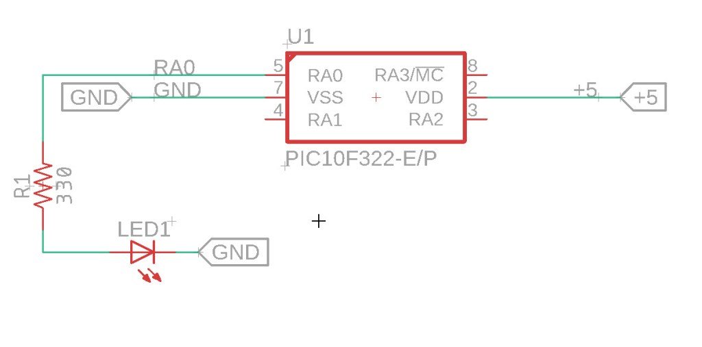
The Circuit

Setting Up Timer0 and Interrupts
The following code demonstrates how to set up Timer0 and interrupts to create a delay timer that can blink an LED on PORTA.0.
/*
 * File:   isr_timer.c
 * Author: Jamie
 *
 * Created on 9/13/2021, 8:56 PM
 */


#include <xc.h>
#include <stdint.h>

#pragma config FOSC = INTOSC  // Oscillator Selection
#pragma config BOREN = ON    // Brown-out Reset
#pragma config WDTE = OFF    // Watchdog Timer
#pragma config PWRTE = ON    // Power-up Timer
#pragma config MCLRE = OFF   // MCLR Pin Function Select bit->MCLR pin function is digital input, MCLR internally tied to VDD
#pragma config CP = OFF      // Code Protection
#pragma config LVP = OFF     // Low-Voltage Programming
#pragma config LPBOR = ON    // Brown-out Reset Selection bits
#pragma config BORV = LO    // Brown-out Reset Voltage Selection
#pragma config WRT = OFF    // Flash Memory Self-Write Protection

//Used to calculate the delay time - Change depending on processor Speed
#define _XTAL_FREQ 8000000  //8 MHz (default after Reset)


//Function prototypes
void setup (void);
unsigned long millis(void);
void delay(uint32_t ms);


//Variables
volatile unsigned long timer0_millis = 0;


//interrupt handler
void __interrupt () isr_routine (void) {

//TMR0 = 8;
timer0_millis +=1;  //increase the counter by 1
INTCONbits.TMR0IF = 0; //clear tmr0 irq flag
}

void main(void)
{
    setup();

    while(1)
    {
       LATAbits.LATA0 = 1; //turn on port A.0
       delay(500);
       LATAbits.LATA0 = 0; //turn off port A.0
       delay(500);
    }

}

void setup (void)
{
    //Set Port A0 as output
    TRISAbits.TRISA0 = 0;

    //Clear any analog and port settings
    ANSELA = 0x00;
    LATA = 0x00;

    /*Set TMR0 to use FOSC/4 At 8Mhz the timer with increment at 2Mhz
    That is 500us
    TMR0 will overflow ever 128us. Which is faster than we want - I am aiming for 1ms.
    So lets use a prescaler to get it close
    Assign prescaler to TMR0 With prescaler of 8 we get  500ns * 256 * 8 = 1.024ms
    Then set the prescaler */

    OPTION_REGbits.PSA = 0;
    OPTION_REGbits.PS = 0b010; //prescaler of 8

    //To Start the timer we need to set the clock source to fosc/4 but first clear the timer just to make sure
    TMR0 = 0;
    OPTION_REGbits.T0CS = 0;

    //Assign interrupt to timer
    INTCONbits.TMR0IF = 0; //clear tmr0 irq flag
    INTCONbits.TMR0IE = 1; //enable tmr0 irq enable
    INTCONbits.GIE = 1; //enable global interrupts
}


//Reads the MS variable
unsigned long millis(void)
{
	unsigned long m;
	// disable interrupts while we read timer0_millis or we might get an
	// inconsistent value (e.g. in the middle of a write to timer0_millis)
	INTCONbits.GIE = 0;
	m = timer0_millis;
    INTCONbits.GIE = 1;

	return m;
}


//Delay based on the number of MS
void delay(uint32_t ms)
{
    //Get the timer value as we go into the delay
	uint32_t start = millis();

    //We wait here until while current timer value, minus the start value, is less than the value we want
	while (millis() - start < ms){}

}
How the Code Works
Device Configuration:
- The configuration bits set various hardware options, such as oscillator selection, brown-out reset, and power-up timer settings.
Setup Function:
- Disables the analog function on PORTA.0 and sets it as an output.
- Configures Timer0 with an internal clock source, assigns the prescaler, and enables the Timer0 interrupt and global interrupts.
Interrupt Service Routine (ISR):
- Checks if Timer0 caused the interrupt.
- Clears the Timer0 interrupt flag and resets the Timer0 register.
- Increments a counter
Advantages of Using Interrupt-Based Delay Timer
- Code Efficiency: The interrupt-based approach uses less code space compared to the
__delay_ms()macro. - Flexibility: The delay timer can be dynamically adjusted based on various inputs, such as analog values, making it suitable for more complex applications.
Summary
By replacing the __delay_ms() macro with an interrupt-based delay timer using Timer0, you can create a more efficient and flexible timing solution with the PIC10F322 microcontroller. This method reduces code space usage and allows for variable delays, enhancing the versatility of your microcontroller projects. In the next post, we will explore using the analog input functions of the PIC10F322 to further enhance our delay timer.
Need a Creator Alchemist on Your Project?
I’m available for hire—consulting, systems design, embedded tech, creative problem-solving, or anything in between.
If you’ve got a project that needs someone who can think it through and build it out, I’m interested.
👉 Let’s Talk
jamie@jamiestarling.com
