Table of Contents
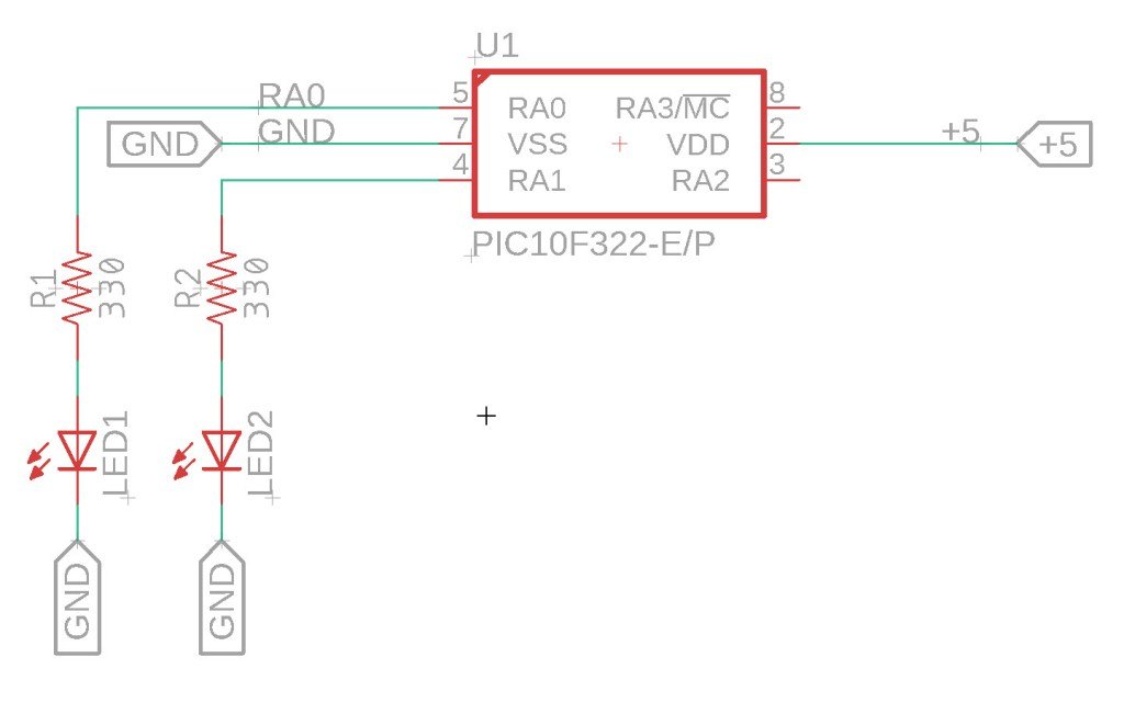
Looking for a way to create eye-catching model train level crossing lights? This guide provides simple XC8 code for the PIC10F322 microcontroller to create a dual alternating flasher. Perfect for model train enthusiasts or anyone needing a basic attention-getting LED flasher.
The Circuit

XC8 Code for Dual Alternating Flasher
Here’s the complete XC8 code to make two LEDs connected to PortA.0 and PortA.1 alternately flash:
/*
 * File:  dual_flasher.c
 * Author: Jamie Starling - GizoFoundry.com
 *
 * Created on:  September 2, 2021, 7:45 PM
 *
 * Code provided as-is.
 */

#include <xc.h>
#include <stdint.h>

//Device Configuration
#pragma config FOSC = INTOSC  // Oscillator Selection
#pragma config BOREN = ON    // Brown-out Reset
#pragma config WDTE = OFF    // Watchdog Timer
#pragma config PWRTE = ON    // Power-up Timer
#pragma config MCLRE = OFF   // MCLR Pin Function Select bit->MCLR pin function is digital input, MCLR internally tied to VDD
#pragma config CP = OFF      // Code Protection
#pragma config LVP = OFF     // Low-Voltage Programming
#pragma config LPBOR = ON    // Brown-out Reset Selection bits
#pragma config BORV = LO    // Brown-out Reset Voltage Selection
#pragma config WRT = OFF    // Flash Memory Self-Write Protection

//Used to calculate the delay time - Change depending on processor Speed
#define _XTAL_FREQ 8000000  //8 MHz (default after Reset)

#define DELAY_TIME 1000   //delay time value


//Prototypes
void setup(void);
void blink_led(void);


void main(void)
{
    setup();

    while(1)
    {
      blink_led();
    }
}

void setup(void)
{
    ANSELAbits.ANSA0 = 0; //Disable Analog A0
    ANSELAbits.ANSA1 = 0; //Disable Analog A1

    TRISAbits.TRISA0 = 0; //Set Port.A0 as output
    TRISAbits.TRISA1 = 0; //Set Port.A1 as output
}

void blink_led(void)
{

    LATAbits.LATA0 = 1;  //Set Port.A0 High (turn on LED)
    LATAbits.LATA1 = 0;  //Set Port.A1 Low  (turn off LED)
    __delay_ms(DELAY_TIME);  //delay


    LATAbits.LATA0 = 0;  //Set Port.A0 Low  (turn off LED)
    LATAbits.LATA1 = 1;  //Set Port.A1 High (turn on LED)
    __delay_ms(DELAY_TIME); //delay
}
How to Customize the Blink Interval
The default blink interval is set to one second. You can adjust the interval by changing the #define DELAY_TIME 1000 line in the code. The value is in milliseconds, so 1000 ms equals 1 second. For example:
For a 500 ms interval:
#define DELAY_TIME 500
For a 2-second interval:
#define DELAY_TIME 2000
Summary
This guide provides a straightforward way to create a dual alternating flasher using the PIC10F322 microcontroller and XC8 compiler. Whether you’re into model trains or need a simple attention-getting flasher, this project is a great starting point. Follow the circuit setup and use the provided code to get your LEDs flashing in no time.
Need a Creator Alchemist on Your Project?
I’m available for hire—consulting, systems design, embedded tech, creative problem-solving, or anything in between.
If you’ve got a project that needs someone who can think it through and build it out, I’m interested.
👉 Let’s Talk
jamie@jamiestarling.com
