Table of Contents
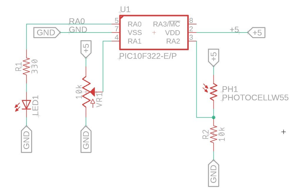
In this tutorial, we will create a light-activated switch using the PIC10F322 microcontroller and the XC8 compiler. By utilizing the ADC module, we can use a photoresistor and a potentiometer to control an LED based on ambient light levels. The potentiometer allows us to adjust the light threshold that triggers the LED.
Setup
- RA0: LED
- RA1: Potentiometer
- RA2: Photoresistor (voltage increases with light intensity)
High-Level Overview
- Hardware Initialization:
- Configure RA0 as an output.
- Configure RA1 and RA2 as analog inputs.
- Main Loop:
- Continuously read the values from the potentiometer and photoresistor.
- Compare the values: if the photoresistor value is greater than the potentiometer value, turn on the LED; otherwise, turn it off.
Detailed Explanation
Hardware Configuration
- LED (RA0):
- Set as an output to indicate light detection.
- Potentiometer (RA1):
- Configured as an analog input to adjust the light sensitivity threshold.
- Photoresistor (RA2):
- Configured as an analog input to measure ambient light levels.
The Circuit…

The Code
The code reads the values from the potentiometer and photoresistor, compares them, and controls the LED accordingly. If the light level detected by the photoresistor exceeds the threshold set by the potentiometer, the LED turns on.
/*
 * File:   adc_photo.c
 * Author: Jamie
 *
 * Created on 9/14/2021, 8:04 PM
 */

#include <xc.h>
#include <stdint.h>

//Device Configuration
#pragma config FOSC = INTOSC  // Oscillator Selection
#pragma config BOREN = ON    // Brown-out Reset
#pragma config WDTE = OFF    // Watchdog Timer
#pragma config PWRTE = ON    // Power-up Timer
#pragma config MCLRE = OFF   // MCLR Pin Function Select bit->MCLR pin function is digital input, MCLR internally tied to VDD
#pragma config CP = OFF      // Code Protection
#pragma config LVP = OFF     // Low-Voltage Programming
#pragma config LPBOR = ON    // Brown-out Reset Selection bits
#pragma config BORV = LO    // Brown-out Reset Voltage Selection
#pragma config WRT = OFF    // Flash Memory Self-Write Protection

//Used to calculate the delay time - Change depending on processor Speed
#define _XTAL_FREQ 8000000  //8 MHz (default after Reset)

//Function prototypes
void setup (void);
uint8_t ADC_Read(uint8_t channel);


void main(void)
{
    setup();

    uint8_t pot_value;  //Var for Potentiometer
    uint8_t light_value; //Var for photoresistor values

    while(1){

        pot_value = ADC_Read(1);
        light_value = ADC_Read(2);

        //Check values - turn on LED if light is over the set value - otherwise off
        if (light_value > pot_value){
            LATAbits.LATA0 = 1;
        }
        else{
             LATAbits.LATA0 = 0;
        }

    }
}


void setup(){

    //Pin LED is connected to
    TRISAbits.TRISA0 = 0;  //Make pin Output RA0
    ANSELAbits.ANSA0 =0;   //Disable Analog RA0
    LATAbits.LATA0 = 0;     //Make the output Low RA0

    //Setup for pin that the POT is connected to
    TRISAbits.TRISA1 = 1;  //Make pin Input RA1
    ANSELAbits.ANSA1 =1;   //Enable Analog RA1

     //Setup for pin that the Photoresistor is connected to
    TRISAbits.TRISA2 = 1;  //Make pin Input RA2
    ANSELAbits.ANSA2 =1;   //Enable Analog RA2

    //Set Analog conversion clock FOSC/32, since we are running 8Mhz, we need to have a conversion time at or greater 1uS
    //FOSC/32 will give us 4uS
    ADCONbits.ADCS = 0b010;

    //Select the Analog channel - RA1 or AN1
    ADCONbits.CHS = 0b001;

    //Turn on the ADC module
    ADCONbits.ADON = 1;
}


uint8_t ADC_Read(uint8_t channel){
    //Uses the channel input to select the ADC channel - valid input is 0,1,2
    //Starts the ADC read and waits until a conversion is complete before returning
    //Returns the ADC value

    switch (channel){
        case 0  :
                //Select the Analog channel - RA0 or AN0
                ADCONbits.CHS = 0b000;
                break;

        case 1  :
                //Select the Analog channel - RA1 or AN1
                ADCONbits.CHS = 0b001;
                break;

        case 2  :
                //Select the Analog channel - RA2 or AN2
                ADCONbits.CHS = 0b010;
                break;
    }


    __delay_ms(10);  //Wait 10ms for ADC input to become stable


    ADCONbits.GO_nDONE = 1;  //Start the conversion

    while (ADCONbits.GO_nDONE == 1){
        NOP();
    }

    return ADRES;
}
Future Improvements
This project is a simple demonstration of using a light-activated switch. Here are a few improvements and additional features you could implement:
- Debounce Functionality:
- To avoid rapid on/off switching due to small fluctuations in light levels, add a debounce mechanism or a short delay before checking the light level again.
- Control Larger Loads:
- Replace the LED with a relay driven by a transistor to control larger loads, such as motors or other high-power devices.
- Adjustable Sensitivity:
- Experiment with different potentiometer values and ADC scaling factors to fine-tune the sensitivity of the light-activated switch.
Summary
By following this tutorial, you can create a light-activated switch using the PIC10F322 microcontroller and XC8 compiler. This project demonstrates the integration of ADC and digital I/O to control an LED based on ambient light levels, providing a foundation for more advanced applications.
Need a Creator Alchemist on Your Project?
I’m available for hire—consulting, systems design, embedded tech, creative problem-solving, or anything in between.
If you’ve got a project that needs someone who can think it through and build it out, I’m interested.
👉 Let’s Talk
jamie@jamiestarling.com
