Table of Contents
How to Build Basic Astable Circuits with PIC10F322 NCO as a 555 Timer Alternative
In this guide, we’ll explore using the PIC10F322’s Numerically Controlled Oscillator (NCO) as an alternative to the 555 timer for creating basic astable circuits. The NCO offers a flexible and precise way to generate astable outputs, providing frequencies up to 500kHz using the internal clock.
Understanding the NCO
The NCO in the PIC10F322 consists of an Adder, Increment Register, and Accumulator. On each rising edge of the input clock, the increment register value (16 bits) is added to the accumulator value (20 bits). When the accumulator overflows, it triggers a selectable action: outputting a fixed duty cycle, generating a pulsed frequency, or causing an interrupt.
Setting Up the NCO for a 500kHz Output
To generate a 500kHz clock signal on PORTA.2, configure the NCO as follows:
Select the Clock Source:
NCO1CLKbits.N1CKS = 0b01; // FOSC (Internal Clock)Set the Increment Register to Maximum:
NCO1INCL = 0xFF;
NCO1INCH = 0xFF;
Set the NCO to Fixed Duty Cycle Mode:
NCO1CONbits.N1PFM = 0; // Fixed Duty Cycle500kHz clock signal that is generated.

Changing the Frequency
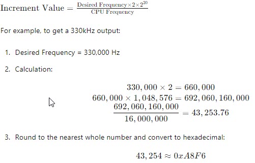
To generate different frequencies, use the following formula:

Replace the increment register value:
NCO1INCL = 0xF6;
NCO1INCH = 0xA8;
330Khz Output Example

Additional Considerations
- NCO Clock Source Selection Bits:
11 = LC1OUT10 = HFINTOSC (16 MHz)01 = FOSC00 = NCO1CLK pin
- Using External Clock Sources: You can use the NCO1CLK pin as a clock input to provide your own clock source, with the NCO dividing this clock as needed.
- Pulse Frequency Mode: In this mode, the NCO generates a pulse on accumulator overflow, with the pulse width defined by
N1PWS<2:0>bits:111 = 128 NCO clock periods110 = 64 NCO clock periods101 = 32 NCO clock periods100 = 16 NCO clock periods011 = 8 NCO clock periods010 = 4 NCO clock periods001 = 2 NCO clock periods000 = 1 NCO clock period
Example Code
Below is a complete example code to set up the NCO for generating a 500kHz output on PORTA.2:
/*
 * File:  NCO_example.c
 * Author: Jamie Starling - GizoFoundry.com
 *
 * Created on:  September 10, 2021, 7:45 PM
 *
 * Code/Circuit provided as-is.
 */


#include <xc.h>
#include <stdint.h>

//Device Configuration
#pragma config FOSC = INTOSC  // Oscillator Selection
#pragma config BOREN = ON    // Brown-out Reset
#pragma config WDTE = OFF    // Watchdog Timer
#pragma config PWRTE = ON    // Power-up Timer
#pragma config MCLRE = OFF   // MCLR Pin Function Select bit->MCLR pin function is digital input, MCLR internally tied to VDD
#pragma config CP = OFF      // Code Protection
#pragma config LVP = OFF     // Low-Voltage Programming
#pragma config LPBOR = ON    // Brown-out Reset Selection bits
#pragma config BORV = LO    // Brown-out Reset Voltage Selection
#pragma config WRT = OFF    // Flash Memory Self-Write Protection

//Used to calculate the delay time - Change depending on processor Speed
#define _XTAL_FREQ 16000000  //16Mhz


//Prototypes
void setup(void);


void main(void)
{
    setup();

    while(1)
    {
    }
}

void setup(void)
{
    //Set the System Clock - You can change this to match the setting you are looking for
    OSCCONbits.IRCF = 0b111;  //Set System Clock to 16Mhz FOSC/4 = 4Mhz

    TRISAbits.TRISA2 = 0; //Make sure to Set A2 to output - otherwise does not work.

    NCO1CLKbits.N1CKS = 0b01; //Clock Source Select bits - Set to FOSC
    NCO1INC  = 0xFFFF; //Adder value
    NCO1CONbits.N1PFM = 0; //NCO operates in Fixed Duty Cycle mode

     NCO1CONbits.N1EN = 1; //Enable NCO
     NCO1CONbits.N1OE = 1; //Enable Output
}
Summary
Using the PIC10F322’s NCO as a replacement for the 555 timer in astable circuits provides a highly flexible and precise solution. By configuring the NCO with specific increment values, you can generate a wide range of frequencies. This guide provides the necessary setup and code to create an astable multivibrator, making it a valuable tool for various applications.
Need a Creator Alchemist on Your Project?
I’m available for hire—consulting, systems design, embedded tech, creative problem-solving, or anything in between.
If you’ve got a project that needs someone who can think it through and build it out, I’m interested.
👉 Let’s Talk
jamie@jamiestarling.com
