Table of Contents
PIC10F322 Button Debounce Tutorial : Step-by-Step XC8 Code
Switch debouncing is essential when working with switches and digital circuits. Without debouncing, a single press can register as multiple presses due to the mechanical nature of switches. Here, we provide code to debounce a signal on the inputs of the PIC10F320 and PIC10F322 microcontrollers.
How Debouncing Works
The provided function input_debounce_A2(void) monitors the state of pin A2. It ensures that a single press or release of a button is registered correctly by eliminating any noise or false triggers.
Explanation of the Debouncing Process
- Initial Input Check:
- The function compares the input value of pin A2 to the desired trigger value (logic 0 in this case).
- Delay:
- The function waits for a specified amount of time (50ms in this example) using
__delay_ms(50). This delay helps to filter out any noise or false readings.
- The function waits for a specified amount of time (50ms in this example) using
- Second Input Check:
- After the delay, the function checks the input value of pin A2 again.
- Comparison:
- If the current value matches the initially sampled value, the function returns
1(TRUE), indicating a valid button press. - If the values do not match, it returns
0(FALSE), indicating that the input was not stable.
- If the current value matches the initially sampled value, the function returns
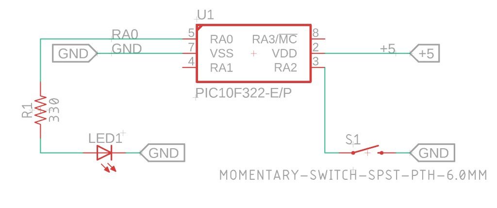
The Circuit

Debouncing Code
Below is the complete code for debouncing an input signal on pin A2 using the XC8 compiler with the PIC10F320 and PIC10F322 microcontrollers:
/*
 * File:  debounce_example.c
 * Author: Jamie Starling - GizoFoundry.com
 *
 * Created on:  September 7, 2021, 7:45 PM
 *
 * Code provided as-is.
 */

#include <xc.h>
#include <stdint.h>

//Device Configuration
#pragma config FOSC = INTOSC  // Oscillator Selection
#pragma config BOREN = ON    // Brown-out Reset
#pragma config WDTE = OFF    // Watchdog Timer
#pragma config PWRTE = ON    // Power-up Timer
#pragma config MCLRE = OFF   // MCLR Pin Function Select bit->MCLR pin function is digital input, MCLR internally tied to VDD
#pragma config CP = OFF      // Code Protection
#pragma config LVP = OFF     // Low-Voltage Programming
#pragma config LPBOR = ON    // Brown-out Reset Selection bits
#pragma config BORV = LO    // Brown-out Reset Voltage Selection
#pragma config WRT = OFF    // Flash Memory Self-Write Protection

//Used to calculate the delay time - Change depending on processor Speed
#define _XTAL_FREQ 16000000  //16Mhz

//Prototypes
void setup(void);
uint8_t input_debounce_A2(void);


void main(void)
{
    setup();

    while(1)
    {
        uint8_t switch_status = 0;
        switch_status = input_debounce_A2();

        //The above is more long hand, it can be simplified down to..
        //if (input_debounce_A2()) - instead of creating a variable, reading the results into it - and compairing that variable,

        if (switch_status == 1)
        {
           LATAbits.LATA0 = 1;
        }

        else
        {
            LATAbits.LATA0 = 0;
        }

    }
}

void setup(void)
{

    //Disable analog for A.0, set as Output, Set to Low
    ANSELAbits.ANSA0 = 0;
    TRISAbits.TRISA0 = 0; //A0 Output
    LATAbits.LATA0 = 0;  //Put A0 low

    //Setup A.2 as input with WPU
    ANSELAbits.ANSA2 = 0;
    TRISAbits.TRISA2 = 1;
    WPUAbits.WPUA2 = 1; //Enable Weakpull up on A2
    OPTION_REGbits.nWPUEN = 0; //Requires being enabled in option reg as well

    //Set the System Clock - You can change this to match the setting you are looking for
    OSCCONbits.IRCF = 0b111;  //Set System Clock to 16Mhz FOSC/4 = 4Mhz


}

/*reads the input on A2 to see if it is low - we have a pullup here
 *so a low input would indicate that the switch that is tied to ground is being pressed
 *If low - we wait 50ms and read the status again
 *If low after 50ms, we return 1 to be true the switch is being pressed, otherwise 0 is returned.
 *You also can adjust the value of the delay and do something like 1 second, which would require
 *the switch to be held for 1 second before something happens. */
uint8_t input_debounce_A2(void)
{
    if (PORTAbits.RA2 == 0)
    {
        __delay_ms(50);

        if (PORTAbits.RA2 == 0)
        {
            return 1;
        }

    return 0;
    }

    return 0;
}
How to Use This Code
- Initialization:
- The
setup()function configures the necessary settings, including disabling the analog function on PortA, setting RA2 as an input, and enabling the weak pull-up resistor on RA2.
- The
- Debounce Function:
- The
input_debounce_A2()function checks the state of RA2, waits for 50 ms, and checks the state again. If both readings are logic 0, it returns1(TRUE).
- The
- Main Loop:
- The main loop continuously checks the debounced state of RA2. If a button press is confirmed, it performs an action (e.g., toggling an LED connected to RA0).
Troubleshooting
Issues with Weak Pull-Ups on Other Pins: If the weak pull-up resistors do not work on other pins (e.g., RA0 and RA1), it might be due to interference from an In-Circuit Debugger (ICD). Disconnecting the ICD and powering the circuit from an independent power supply should resolve this issue.
Summary
This guide provides a clear explanation and example code for debouncing an input signal on the PIC10F320 and PIC10F322 microcontrollers using the XC8 compiler. By following this guide, you can ensure reliable button presses in your digital circuits, eliminating the noise and false triggers commonly associated with mechanical switches.
Need a Creator Alchemist on Your Project?
I’m available for hire—consulting, systems design, embedded tech, creative problem-solving, or anything in between.
If you’ve got a project that needs someone who can think it through and build it out, I’m interested.
👉 Let’s Talk
jamie@jamiestarling.com
