Contents
PIC10F322 MCU Overview : For in-depth technical details, please refer to the Microchip datasheet. This overview provides a high-level summary to help you get started with the PIC10F322 microcontroller.
The Major difference between the PIC10F320 and PIC10F322
The major difference (and only) between the PIC10F320 and PIC10F322
- PIC10F320 has 256 words of program memory
- PIC10F322 has 512 words of program memory
The PIC10F322 has double the program storage space.
Both PIC10F320 and PIC10F322 Come With
4 I/O Pins: Labeled RA0 – RA3
- RA3 (shared MCLR Pin) is input only.
- I/O Pins can sink/source current up to 50mA
- Individually selectable weak pull-ups
- Interrupt on change
Two Timers: TMR0 and TMR2
- Timer0: 8 bit Timer/Counter with Programmable Prescaler
- Timer2: 8 bit Timer/Counter with 8-Bit Period Register, Prescaler and Postscaler
(Don’t ask – why did it jump from Timer0 to Timer2.. What happened to 1?)
Two PWM modules:
- 10bit PWM – Max Frequency of 16kHz
A/D (Analog Digital) Converter:
- 8 bits – three channels (pins RA0, RA1, RA2)
Configurable Logic Cell (CLC):
- Software selectable logic functions including:
- AND/OR/XOR/D Flop/D Latch/SR/JK
Numerically Controlled Oscillator (NCO):
- 20-bit accumulator
- 16-bit increment
- Linear frequency control
- High-speed clock input
- Selectable Output modes
- Fixed Duty Cycle (FDC)
- Pulse Frequency (PF) mode
Complementary Waveform Generator (CWG):
- Selectable falling and rising edge dead-band control
- Polarity control
- Two auto-shutdown sources
- Multiple input sources: PWM, CLC, NCO
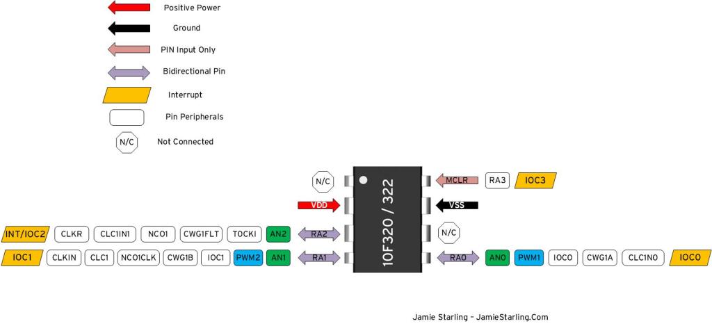
A pin out diagram for the PIC10F322 and PIC10F320

Need a Creator Alchemist on Your Project?
I’m available for hire—consulting, systems design, embedded tech, creative problem-solving, or anything in between.
If you’ve got a project that needs someone who can think it through and build it out, I’m interested.
👉 Let’s Talk
jamie@jamiestarling.com
