Contents
In my work with 8-bit microcontrollers, including the PIC10F322, I often rely on a +5V power supply. It’s a tried-and-true method, appreciated for its reliability.
Precision Power Regulation for the PIC10F322
To ensure optimal performance of the PIC10F322, a well-designed power regulation circuit is essential. This circuit takes an input voltage and adjusts it to the precise voltage required by the microcontroller. Operating beyond the recommended 5V can damage the PIC10F322, making proper regulation crucial.
Elegant Breadboard Power Solutions
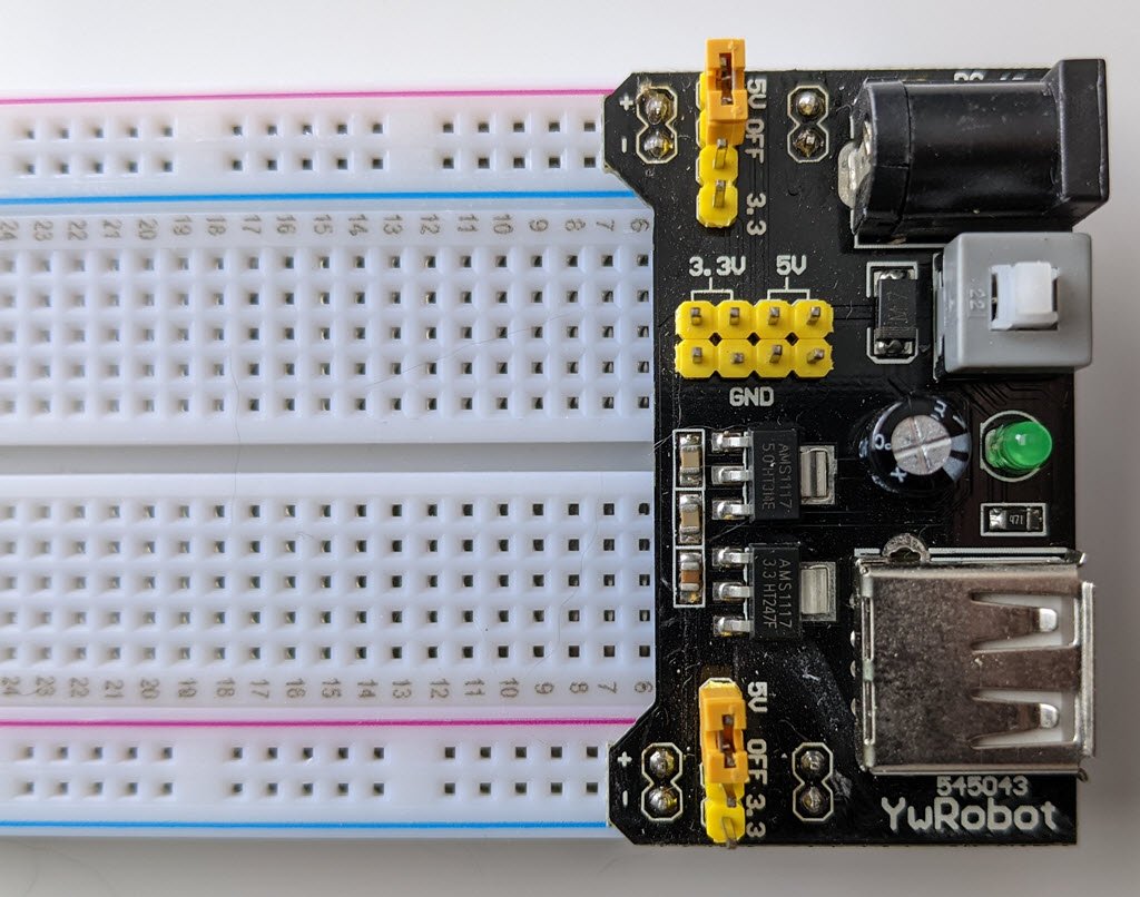
For a quick and efficient power setup, consider a breadboard power regulator. These regulators, available on platforms like eBay and Amazon, accept up to a 12V input and provide adjustable outputs of 5V or 3.3V via jumpers. They even allow for dual-rail operation, providing 5V on one rail and 3.3V on the other. Featuring an on/off switch, these regulators simplify your power management.
To power the PIC10F322:
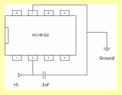
- Connect the +5V to VDD (pin 2 of the PDIP package)
- Connect the ground (0V) to VSS (pin 7 of the PDIP package)

Ensuring Stability with Decoupling Capacitors
A crucial aspect of powering your microcontroller is the inclusion of a decoupling capacitor, or bypass capacitor. These capacitors should be placed as close as possible to the integrated circuit (IC) on the PCB. Once charged, they stabilize the input voltage by filtering out noise and providing a steady power source, crucial for the sensitive components of your PIC10F322.
Neglecting decoupling capacitors can lead to erratic behavior in your microcontroller, such as skipped instructions or abnormal operation. A .1μF capacitor is typically sufficient for most applications

While it seems like this might create a short from power to ground, only high-frequency signals can run through the capacitor to ground. The DC signal will go to the IC, just as desired. Another reason these are called bypass capacitors is because the high frequencies (in the kHz-MHz range) bypass the IC, instead running through the capacitor to get to ground.
When physically placing decoupling capacitors, they should always be located as close as possible to an IC. The further away they are, the less effective they’ll be.
For most of our work, a .1uf cap is enough to take care of this.
Creating a Custom 5V Regulator
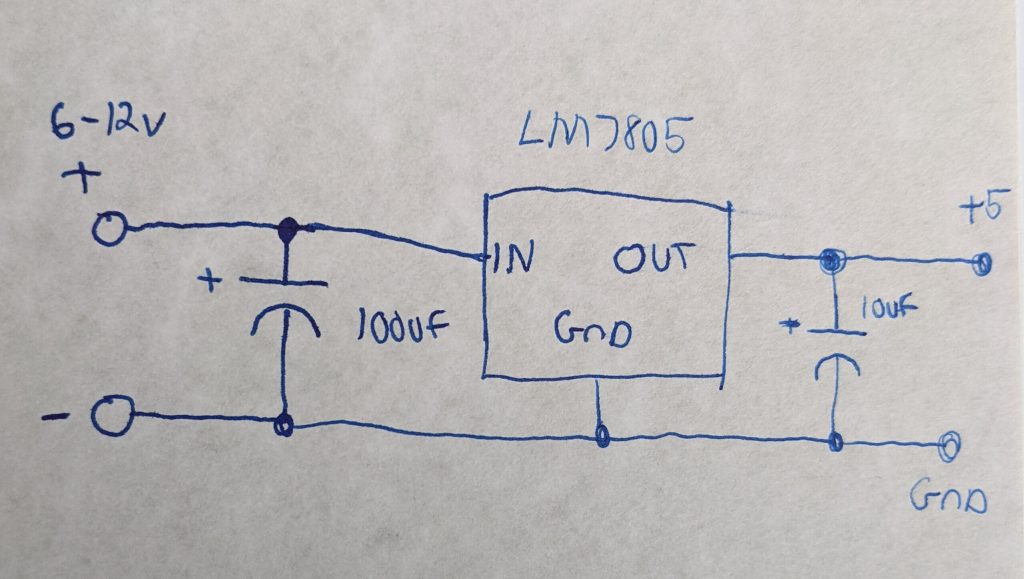
For those seeking a tailored power solution, creating your own +5V regulator is a rewarding endeavor. Below is a quick hand-drawn setup to guide you in crafting a bespoke regulator.
This custom approach allows you to design a power supply that perfectly fits your project’s unique requirements, ensuring both elegance and precision.

Need a Creator Alchemist on Your Project?
I’m available for hire—consulting, systems design, embedded tech, creative problem-solving, or anything in between.
If you’ve got a project that needs someone who can think it through and build it out, I’m interested.
👉 Let’s Talk
jamie@jamiestarling.com
