Table of Contents
Replacing the 555 Timer with PIC10F322: Cascaded Timer Applications
In this guide, we’ll explore how to use the PIC10F322 microcontroller as a replacement for the 555 timer in cascaded timer applications. Cascaded timers allow for sequential triggering of outputs, which can be useful in various applications like lighting sequences, motor control, and more.
Cascaded Timer Overview
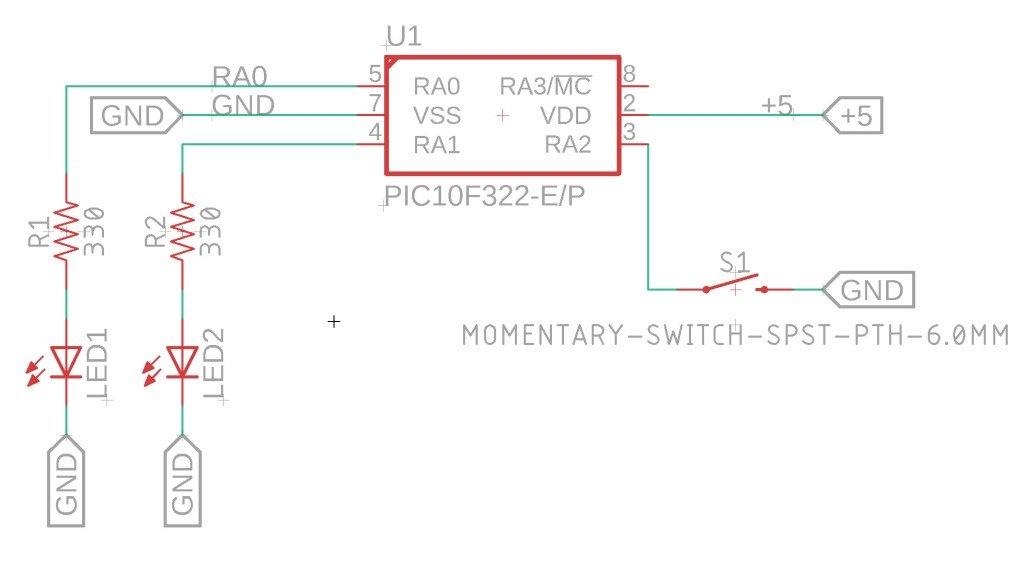
In this example, when the input on PORTA.2 goes low, the following sequence occurs:
- PORTA.0 goes high for 1 second, then goes low.
- PORTA.1 goes high for 1 second, then goes low.
The on-time duration can be adjusted by changing the value of PulseOut_Time.
The Circuit

XC8 Code for Cascaded Timer
Here’s the complete XC8 code to set up the cascaded timer functionality using the PIC10F322 microcontroller:
/*
 * File:   cascaded_timer.c
 * Author: Jamie
 *
 * Created on 9/13/2021, 8:56 PM
 */


#include <xc.h>
#include <stdint.h>

//Device Configuration
#pragma config FOSC = INTOSC // Oscillator Selection
#pragma config BOREN = ON // Brown-out Reset
#pragma config WDTE = OFF // Watchdog Timer
#pragma config PWRTE = ON // Power-up Timer
#pragma config MCLRE = OFF // MCLR Pin Function Select bit->MCLR pin function is digital input, MCLR internally tied to VDD
#pragma config CP = OFF // Code Protection
#pragma config LVP = OFF // Low-Voltage Programming
#pragma config LPBOR = ON // Brown-out Reset Selection bits
#pragma config BORV = LO // Brown-out Reset Voltage Selection
#pragma config WRT = OFF // Flash Memory Self-Write Protection

//Used to calculate the delay time – Change depending on processor Speed
#define _XTAL_FREQ 8000000 //8Mhz

#define PulseOut_Time 1000

//Prototypes
void setup(void);
void cascade(void);
uint8_t input_debounce_A2(void);


void main(void){
    setup();

    while(1)
    {
        if (input_debounce_A2() == 1){
        cascade();
        }

    }
}

void setup(void){

    //Disable analog for A0, set as Output, Set to Low
    ANSELAbits.ANSA0 = 0;
    TRISAbits.TRISA0 = 0; //A0 Output
    LATAbits.LATA0 = 0; //Put A0 low

    //Disable analog for A1, set as Output, Set to Low
    ANSELAbits.ANSA1 = 0;
    TRISAbits.TRISA1 = 0; //A1 Output
    LATAbits.LATA1 = 0; //Put A1 low

    //Setup A2 as input with WPU
    ANSELAbits.ANSA2 = 0;
    TRISAbits.TRISA2 = 1;
    WPUAbits.WPUA2 = 1; //Enable Weakpull up on A.2
    OPTION_REGbits.nWPUEN = 0; //Requires being enabled in option reg as well
}

/*reads the input on A2 to see if it is low – we have a pullup here
*so a low input would indicate that the switch that is tied to ground is being pressed
*If low – we wait 50ms and read the status again
*If low after 50ms, we return 1 to be true the switch is being pressed, otherwise 0 is returned.
*You also can adjust the value of the delay and do something like 1 second, which would require
*the switch to be held for 1 second before something happens. */
uint8_t input_debounce_A2(void){

    if (PORTAbits.RA2 == 0){
    __delay_ms(50);

    if (PORTAbits.RA2 == 0){
        return 1;
    }

    return 0;
    }

    return 0;
}

void cascade(void)
{
    LATAbits.LATA0 = 1; //A0 on
    LATAbits.LATA1 = 0; //A1 off

    __delay_ms(PulseOut_Time);

    LATAbits.LATA0 = 0; //A0 off
    LATAbits.LATA1 = 1; //A1 on

    __delay_ms(PulseOut_Time);

    LATAbits.LATA0 = 0; //A0 off
    LATAbits.LATA1 = 0; //A1 off
}
Need a Creator Alchemist on Your Project?
I’m available for hire—consulting, systems design, embedded tech, creative problem-solving, or anything in between.
If you’ve got a project that needs someone who can think it through and build it out, I’m interested.
👉 Let’s Talk
jamie@jamiestarling.com
