Table of Contents
Understanding and Using Weak Pull-Up Resistors on the PIC10F322 with XC8 : This guide explains how to use the internal Weak Pull-Up (WPU) resistors on the PIC10F322 and PIC10F320 microcontroller. Weak pull-up resistors are helpful in maintaining a stable logic level on a pin when it is not actively driven.
What Are Weak Pull-Up Resistors?
Weak pull-up resistors tie a pin to a positive voltage internally, similar to connecting an external 10K resistor between the pin and the positive rail. This ensures that the pin defaults to a high state (logic level 1) when it is not grounded. If the pin is grounded, it will be pulled to a low state (logic level 0).
Setting Up Weak Pull-Up Resistors
Each GPIO pin on the PIC10F322 can have its weak pull-up resistor enabled individually. Here’s how to set it up:
Enable Weak Pull-Up on a Specific Pin:
WPUAbits.WPUA2 = 1; //Enable Weakpull up on A2
Enable Weak Pull-Ups in the Option Register:
OPTION_REGbits.nWPUEN = 0; //Requires being enabled in option reg as well
Example Code
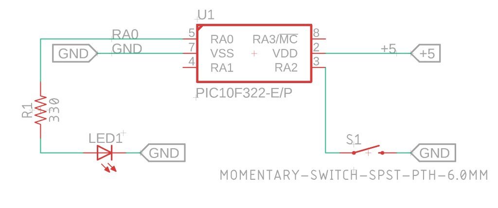
Below is an example demonstrating how to use the weak pull-up resistor on RA2 to control an LED on RA0. A button is connected to RA2, and pressing the button will light up the LED.
The Circuit

XC8 Code for Weak Pull-Up Resistors
Here’s the complete XC8 code to implement the setup described:
/*
 * File:  wpu_example.c
 * Author: Jamie Starling - GizoFoundry.com
 *
 * Created on:  September 7, 2021, 7:45 PM
 *
 * Code provided as-is.
 */


#include <xc.h>
#include <stdint.h>

//Device Configuration
#pragma config FOSC = INTOSC  // Oscillator Selection
#pragma config BOREN = ON    // Brown-out Reset
#pragma config WDTE = OFF    // Watchdog Timer
#pragma config PWRTE = ON    // Power-up Timer
#pragma config MCLRE = OFF   // MCLR Pin Function Select bit->MCLR pin function is digital input, MCLR internally tied to VDD
#pragma config CP = OFF      // Code Protection
#pragma config LVP = OFF     // Low-Voltage Programming
#pragma config LPBOR = ON    // Brown-out Reset Selection bits
#pragma config BORV = LO    // Brown-out Reset Voltage Selection
#pragma config WRT = OFF    // Flash Memory Self-Write Protection

//Used to calculate the delay time - Change depending on processor Speed
#define _XTAL_FREQ 16000000  //16 MHz

//Prototypes
void setup(void);
void check_button(void);


void main(void)
{
    setup();

    while(1)
    {
        check_button();
    }
}

void setup(void)
{
    OSCCONbits.IRCF = 0b111;  //Set System Clock to 16Mhz FOSC 4Mhz

    //Disable analog for A0 and A2
    ANSELAbits.ANSA0 = 0;
    ANSELAbits.ANSA2 = 0;

    TRISAbits.TRISA0 = 0; //A0 Output
    TRISAbits.TRISA2 = 1; //A2 Input

    WPUAbits.WPUA2 = 1; //Enable Weakpull up on A2
    OPTION_REGbits.nWPUEN = 0; //Requires being enabled in option reg as well

    LATAbits.LATA0 = 0;

}

void check_button(void)
{
    //Keep in mind a pullup keeps the pin logic high. TO test for button press - the button when pressed with bring the pin to logic 0 or low.
    if (PORTAbits.RA2 == 0)
    {
        LATAbits.LATA0 = 1;  //Turn on Led when button is pressed
    }

    else
    {
        LATAbits.LATA0 = 0; //Turn off Led when button is released
    }

}
How It Works
- Default State: When the button is not pressed, RA2 is pulled high by the internal weak pull-up resistor, and the LED remains off.
- Button Pressed: When the button is pressed, RA2 is pulled low (logic level 0), causing the LED to light up.
- Button Released: When the button is released, RA2 returns to high (logic level 1), and the LED turns off.
Troubleshooting
If the weak pull-up resistors do not work on other pins (e.g., RA0 and RA1), it might be due to interference from an In-Circuit Debugger (ICD). The ICD can pull these ports low. Disconnecting the ICD and powering the circuit from an independent power supply should resolve this issue.
Summary
This guide demonstrates how to use the internal weak pull-up resistors on the PIC10F322 microcontroller with XC8. By following the circuit setup and using the provided code, you can effectively manage pin states and control external components like LEDs. This method keeps your design clean and removes the need for external pull-up resistors.
Need a Creator Alchemist on Your Project?
I’m available for hire—consulting, systems design, embedded tech, creative problem-solving, or anything in between.
If you’ve got a project that needs someone who can think it through and build it out, I’m interested.
👉 Let’s Talk
jamie@jamiestarling.com
