Table of Contents
Using a Potentiometer with a PIC Microcontroller
You know those little knobs you see on old radios or dimmer switches? The ones that let you turn up the volume or control the brightness of a light? That’s the magic of a potentiometer—sometimes called a “pot” for short. And while it may look like just a simple dial, under the surface, it’s doing a lot more. By changing the resistance as you turn it, a potentiometer gives you a smooth, gradual way to control almost anything.
Understanding What a Potentiometer Does
A potentiometer is essentially a variable resistor. It has three pins:
- One side pin connects to your positive voltage (VCC).
- The other side pin goes to ground (GND).
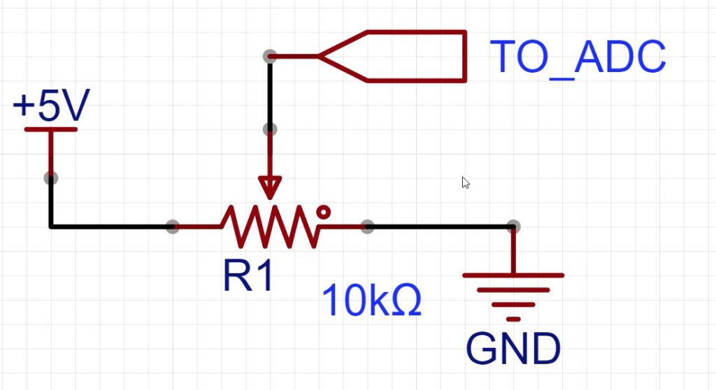
- The middle pin, often called the wiper, is where the magic happens. As you turn the knob, the wiper moves, changing its position between the high and low voltage points. This creates a varying voltage that our PIC can read.
The result? The more you turn the knob, the higher or lower the voltage on that middle pin, giving us a smooth range of values to work with.

Why Use a Potentiometer?
Potentiometers are one of the simplest ways to add analog input to your projects. They’re intuitive, inexpensive, and versatile. Whether you’re building a custom control panel, adjusting sound levels, or just experimenting, a potentiometer is a great way to give your projects a human touch.
Setting Up the Circuit: Connecting the Potentiometer to a PIC
Let’s start with a simple circuit. Here’s how we’ll hook it up:
- Connect the first pin of the potentiometer to 5V on the microcontroller (VCC).
- Connect the second pin to Ground (GND).
- The middle pin—the wiper—goes to the ADC input pin on the PIC microcontroller (for example, AN0 on PortA).
When you turn the knob, the voltage at the wiper changes from 0V (ground) to 5V (VCC), depending on its position. This varying voltage is what we want to read with the PIC’s ADC.
Reading Analog Values: From Voltage to Data
Now comes the fun part—reading those changing voltages and turning them into data we can work with. The PIC’s ADC module will take the analog voltage from the potentiometer and convert it into a digital value that we can read in our code.
For a typical 10-bit ADC (like the one in many PIC microcontrollers), the output value will range from 0 to 1023:
- 0 represents 0V (the lowest value).
- 1023 represents 5V (the highest value).
- Values in between represent everything in between.
So, when the potentiometer is turned all the way down, you’ll get a value close to 0. When it’s turned all the way up, you’ll see a value near 1023. As you slowly turn the knob, you’ll see smooth changes in the numbers.
A World of Possibilities
By understanding how to read a potentiometer with your PIC, you’ve unlocked a powerful way to control your microcontroller projects. From this small, analog input, you can start creating all kinds of interactive applications. Want to make your own control board for a model train layout, adjusting speed and direction with just a turn of a knob? You can. Want to create a lighting system that fades smoothly? You’re halfway there.
With each turn of the dial, you’re not just reading numbers; you’re opening a new channel for creativity and interaction—one that lets you shape the world around you, one step at a time. So go ahead, start turning that knob, and see where it takes you!
Next Post
Using a Potentiometer with a PIC Microcontroller To Change Flash Rate of LED
Need a Creator Alchemist on Your Project?
I’m available for hire—consulting, systems design, embedded tech, creative problem-solving, or anything in between.
If you’ve got a project that needs someone who can think it through and build it out, I’m interested.
👉 Let’s Talk
jamie@jamiestarling.com
