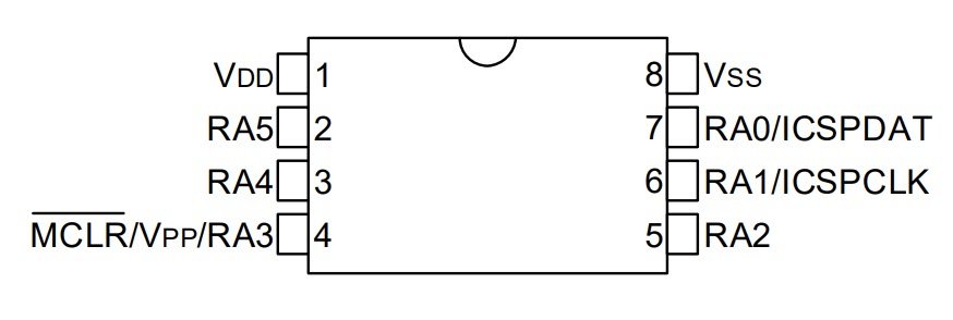
PIC16F15213 MCU Overview.
The PIC16F15213 is a 8 Pin cost effective upgrade from the PIC10F322. This MCU will give you two more I/O pins compared to the PIC10F322 – About 7 times the flash program space, 4x the SRAM space, and various other peripherals such as I2C, EUSART, and SPI.
Don't confuse the PIC16F15213 with the PIC16F15313. Both are 8 pin device and are similar except for some peripherals.

The PIC16F15213:
- Is an 8pin Device – with 6 I/O Pins {Two pins are used for power supply}
- Most Pin functions are mappable
- 1x External Interrupt Pin
- 6x Interrupt-on-change pins – IOC
- Operating Voltage Range: 1.8V to 5.5V
- Max CPU Speed 32Mhz
- Internal or External Clocking
- Has 3.5K of Program Flash Memory
- 256 Bytes of SRAM
- Has Memory Access Partition
- Has Device Information Area
- Timers
- 1x 8 bit timer
- 2x 16 bit timers
- PWM and CCP
- 2X PWM
- 2X CCP
- ADC Analog to Digital Converts
- 1 ADC 10bit Converter
- 5x ADC Channels
- Has 1x MSSP – Host Synchronous Serial Port (I2C / SPI modes)
- Has 1x EUSART – Enhanced Universal Synchronous Asynchronous Receiver Transmitter
- Has Watchdog Timer
- Programming and In-Circuit Debug
- Supports In-Circuit Serial Programming and In-Circuit Debug (VIA two Pins)
Have a Project or Idea!?
Seeking Bespoke Technology Solutions?
Contact me today to discover how personalized, high-end tech solutions can meet your unique requirements.
