Table of Contents
Getting Started with ADC on PIC10F322 Using XC8
The PIC10F322 microcontroller features an Analog-to-Digital Converter (ADC) with three selectable external analog channels. This ADC allows you to convert an analog signal (voltage) into an 8-bit digital value ranging from 0 to 255, which can be used for various applications.
Enabling and Using the ADC
Here’s how to enable the ADC on PORTA.1 and read an analog value:
Step-by-Step Process
Configure the Port:
- Disable the pin output driver:
TRISAbits.TRISA1 = 1; // Make pin PORTA.1 an input
- Configure the pin as analog:
ANSELAbits.ANSA1 = 1; // Enable analog function on PORTA.1
Configure the ADC Module:
- Select ADC conversion clock
ADCONbits.ADCS = 0b010; // Set ADC conversion clock to FOSC/32
Since we are running at 16MHz, this configuration provides a conversion time of 2µs, which meets the requirement of being greater than 1µs.
Select ADC input channel:
ADCONbits.CHS = 0b001; // Select analog channel AN1 (PORTA.1)
Turn on the ADC module:
ADCONbits.ADON = 1; // Enable the ADC module
Start ADC Conversion:
- Initiate conversion by setting the GO/DONE bit
ADCONbits.GO_nDONE = 1; // Start the conversion
Wait for ADC Conversion to Complete:
- Poll the GO/DONE bit until conversion is complete
while (ADCONbits.GO_nDONE == 1) {
    NOP(); // Wait for the conversion to complete
}
Read the ADC Result:
- Retrieve the result from the ADC result register
int adc_value = ADRES; // Read the converted value
Example: Lighting an LED Based on ADC Value
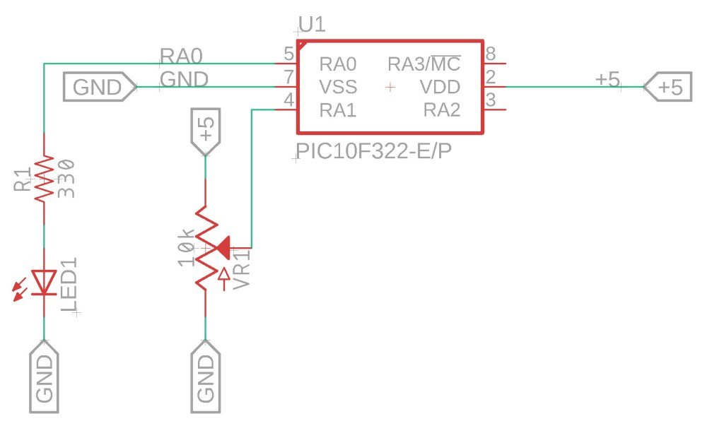
In this example, we’ll use the ADC to read the voltage from a 10k potentiometer connected to PORTA.1. If the ADC value exceeds 128, an LED connected to PORTA.0 will light up.

The Circuit
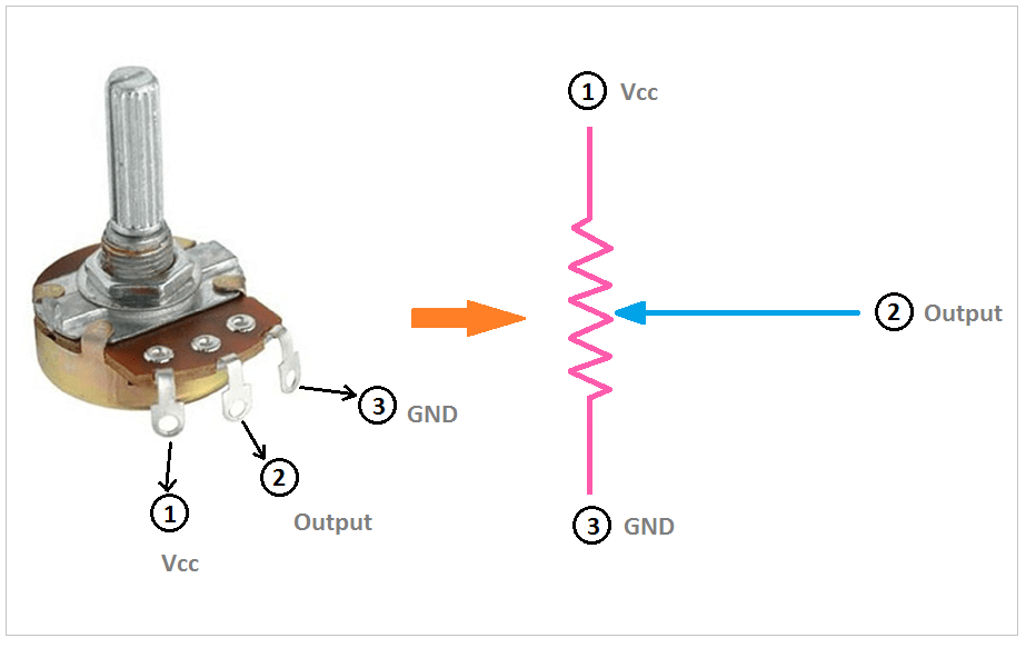
Turn the potentiometer will increase or decrease the output voltage – please note that this voltage should be only used for measurement and not to drive the circuit.

The Code
The code has a 1 second delay before reading the ADC again and checking the value.
/*
 * File:   adc_example.c
 * Author: Jamie
 *
 * Created on 9/14/2021, 8:01 AM
 */


#include <xc.h>
#include <stdint.h>

//Device Configuration
#pragma config FOSC = INTOSC  // Oscillator Selection
#pragma config BOREN = ON    // Brown-out Reset
#pragma config WDTE = OFF    // Watchdog Timer
#pragma config PWRTE = ON    // Power-up Timer
#pragma config MCLRE = OFF   // MCLR Pin Function Select bit->MCLR pin function is digital input, MCLR internally tied to VDD
#pragma config CP = OFF      // Code Protection
#pragma config LVP = OFF     // Low-Voltage Programming
#pragma config LPBOR = ON    // Brown-out Reset Selection bits
#pragma config BORV = LO    // Brown-out Reset Voltage Selection
#pragma config WRT = OFF    // Flash Memory Self-Write Protection

//Used to calculate the delay time - Change depending on processor Speed
#define _XTAL_FREQ 16000000  //16Mhz

//Prototypes
void setup(void);
int ADC_Read(void);

void setup(void){
    //Set the System Clock - You can change this to match the setting you are looking for
    OSCCONbits.IRCF = 0b111;  //Set System Clock to 16Mhz

    //Pin LED is connected to
    TRISAbits.TRISA0 = 0;  //Make pin Output Port.A0
    ANSELAbits.ANSA0 =0;   //Disable Analog Port.A0
    LATAbits.LATA0 = 0;    //Make output low

    TRISAbits.TRISA1 = 1;  //Make pin Input Port.A1
    ANSELAbits.ANSA1 =1;   //Enable Analog Port.A1

    //Set Analog conversion clock FOSC/32, since we are running 16Mhz, we need to have a conversion time at or greater 1uS
    //FOSC/32 will give us 2uS
    ADCONbits.ADCS = 0b010;

    //Select the Analog channel - Port.A1 or AN1
    ADCONbits.CHS = 0b001;

    //Turn on the ADC module
    ADCONbits.ADON = 1;
}

void main(void)
{
    setup();

    while(1){

        int ADC_Value = 0;
        ADC_Value = ADC_Read();

        if (ADC_Value > 128){
            LATAbits.LATA0 = 1;  //Turn ON LED
        }
        else{
            LATAbits.LATA0 = 0;  //Turn OFF LED
        }

    __delay_ms(1000);  //Wait 1 second and do it again

    }
}

int ADC_Read(){
    //Starts the ADC read and waits until a conversion is complete before returning
    //Returns the ADC value
    ADCONbits.GO_nDONE = 1;  //Start the conversion

    while (ADCONbits.GO_nDONE == 1){
        NOP();
    }

    return ADRES;
}
Summary
Using the ADC on the PIC10F322 with XC8 allows you to convert analog signals into digital values for various applications. This guide provides a comprehensive setup for enabling the ADC, configuring the ports, and reading the ADC values. The example demonstrates how to use the ADC to control an LED based on an analog input, making it a practical starting point for more complex projects.
Need a Creator Alchemist on Your Project?
I’m available for hire—consulting, systems design, embedded tech, creative problem-solving, or anything in between.
If you’ve got a project that needs someone who can think it through and build it out, I’m interested.
👉 Let’s Talk
jamie@jamiestarling.com
